Human Centered Design: Enhancing technology for Blind/low-vision users
This was a semester long project for my human centered design course. I worked alongside my teammates Prachitesh Mysorekar and Enrique Nuñez Garcia.
Phase 1: Problem Opportunity Gap
Our problem opportunity gap was originally defined as a voice-to-Braille problem space. However, we initially expanded this to Braille, so as to work with a larger demographic than deafblind individuals. After initial research refined our problem statement as:
How might we provide blind and low vision individuals with adaptive personal technology in order to interpret textual environmental elements and communicate under dynamic conditions?
Phase 2: User Research
Our process for user research included speaking to several Blind/low-vision individuals around the East Bay. I spoke with Ann Wai-Yee Kwong who is the director/coordinator of the new Disability Cultural Community (DCC) Center here at UC Berkeley. Alongside my teammates I also spoke with Frank Welte, Senior Accessible Media and Braille Specialist for San Francisco’s LightHouse for the Blind and Visually Impaired. From discussions with them we realized the project would be better off if we stepped away from a Braille centered direction, since only about 1 in 10 of those with blindness/low-vision in the US are literate in Braille. Instead we decided on trying to create more affordable devices that modify existing technology.
Phase 3: Ideation
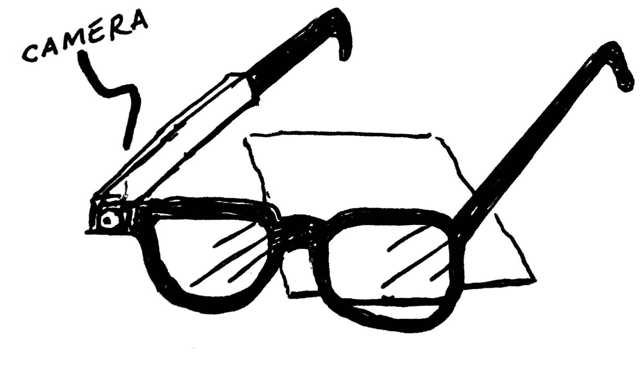
The images below are illustrations I did during our ideation process. From top left to bottom right: ultra light-weight cane, flexible Perkins keyboard, haptic bracelet, text-recognition glasses, handheld text-to-audio device, smartphone compatible Braille generator, smart phone simplifier, text-to-audio ring, and handheld tactile GPS.


Below is my initial illustration for the concept we would end up taking to the prototyping stage: cane proximity scanner. Current smart cane technology with this sort of ability retails for $599. We aimed to create a device with some of the same capabilities for a much lower cost. This device would be able to detect low-hanging obstructions like tree-branches or scaffolding that do not have a footprint and thus are not easily detected by a cane.

An early sketch of a cane with proximity sensing
Below is a short video-clip from HBO’s How To with John Wilson that illustrates the problem opportunity gap.
Below is an image I illustrated of how we intended to create a low-fidelity prototype of the handle.

These were some final ideation sketches before beginning the prototyping process.
Phase 4: Prototyping Process

This is a rendering I made in Fusion 360 of a white cane with our detachable ultrasonic handle

This is a close-up rendering of the handle we designed. On the bottom left is the ultrasonic sensor.
I designed the electronics for the interior, selecting an ultrasonic MB1010 LV-MaxSonar-EZ1 sensor from maxbotix. I also elected to use a teensy 2.0 as the primary microcontroller. For output, I selected a coreless vibration motor.
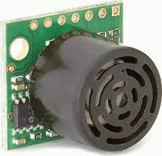
MB1010 LV-MaxSonar-EZ1 ultrasonic sensor
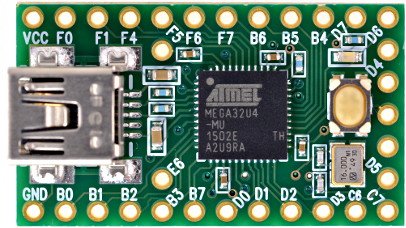
Teensy 2.0 microcontroller from PJRC

A coreless vibration motor similar to one used in the final prototype
Below you can see the prototyping process for the electronics which I iterated on using a breadboard.

Testing the preliminary code and electronics

Final electronics setup where I soldered together the teensy, ultrasonic sensor, and the motor.
The following is code I modified to work with the teensy 2.0 to activate the vibration motor once the sensor detected an object less that 56 inches away.
/*
This code reads the Analog Voltage output from the
LV-MaxSonar sensors
*/
int motorPin = 4;
const int anPin1 = 19;
long distance1;

void setup() {
  Serial.begin(9600);  // sets the serial port to 9600
  pinMode(motorPin, OUTPUT);
}

void read_sensors(){
  /*
  Scale factor is (Vcc/512) per inch. A 5V supply yields ~9.8mV/in
  Arduino analog pin goes from 0 to 1024, so the value has to be divided by 2 to get the actual inches
  */
  distance1 = analogRead(anPin1)/2;
}

void print_all(){
  Serial.print("S1");
  Serial.print(" ");
  Serial.print(distance1);
  Serial.print("inches");
  Serial.println();
}

void loop() {
  read_sensors();
  print_all();
  delay(50);
  while (distance1 <= 56){
    read_sensors();
    print_all();
    digitalWrite(motorPin, HIGH); //vibrate
    delay(1000);  // delay one second
    digitalWrite(motorPin, LOW);  //stop vibrating
    //delay(1000); //wait 50 seconds.
  }
}

Sensing range: from the MB1010 LV-MaxSonar-EZ1 sensor documentation
The ultrasonic sensor can detect between 6 inches and 10 ft away. The reason 56 inches was selected as the threshold for detection was because that is the length of the cane.

Calculations to set threshold for object detection with the ultrasonic sensor
Below is the image of the final functioning low-fidelity prototype, it is powered by 3 coin-cell 1.5v batters, and the components cost less than $50 to create it. The handle was first molded around a real cane with two-part silicone, and then the electronics were attached to it with electrical tape.

The final functional low-fidelity prototype that I constructed. the ultrasonic sensor is on the lower right. The vibration motor in the middle buzzes when objects in an upward direction are detected less than 56 inches away.
Future Directions
Moving forward with this project, I would ideally create a more robust handle by 3D printing it with the objet printers in the advanced materials lab in Jacobs Hall. Additionally I would consider adding a few more motors for more functionality, so that the intensity of the motor reflected the distance away from the object as the user got closer. I would like to receive more feedback from the users we interviewed to see what changes they suggest to improve the design.